Tech Pattern
Grid of randomized geometric shapes with noise-driven density, or your own sprite sheet laid out across the grid.
The Tech Pattern node scatters small geometric glyphs — circles, crosses, squares, diamonds, rings — across a grid, with a noise field driving where they cluster. Switch it to Sprite Sheet mode to lay out frames from an image atlas (or a generator piped into its Sprite Atlas input) instead of the built-in shapes.
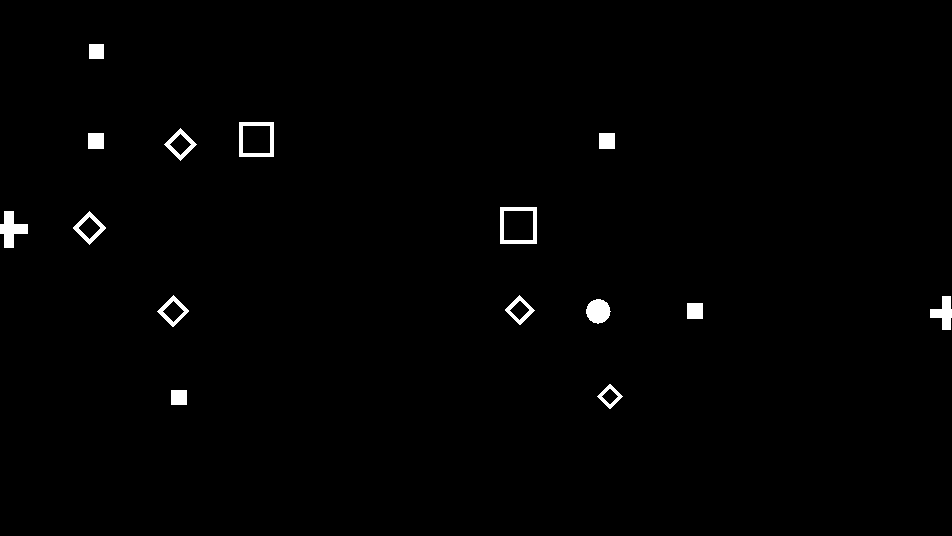
- One texture output; three optional texture inputs (domain warp, sprite atlas, composite)
- Cell Size, Density, Randomness, and Clumping shape the default glyph grid
- Sprite Mode swaps the glyphs for frames from a sprite sheet
- Found in the node graph under Generators as Tech Pattern
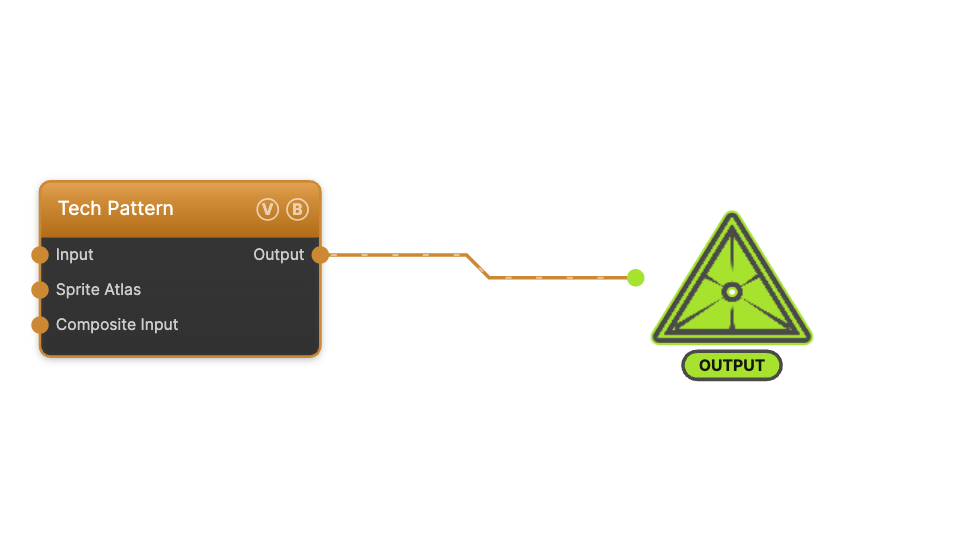
The image on the right is the example patch itself — drag and drop it onto the app (or load it with File → Load) to open the full graph.
Inputs and outputs
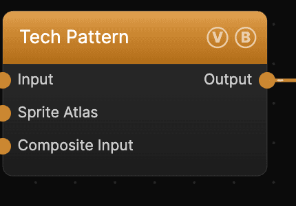
| Port | Type | Purpose |
|---|---|---|
| Input | Texture | Domain warp — the red/green channels displace the sample coordinates |
| Sprite Atlas | Texture | A generator to use as the sprite sheet in Sprite Sheet mode (e.g. Bit Glyphs or Custom GLSL), instead of — or on top of — a dropped image file |
| Composite Input | Texture | Composited under the output with Composite Mode and Composite Mix, which appear once the port is wired |
| Output | Texture | The grayscale glyph grid on black |
The Sprite Atlas port is the second input; it only affects the output when Sprite Mode is set to Sprite Sheet.
Parameters
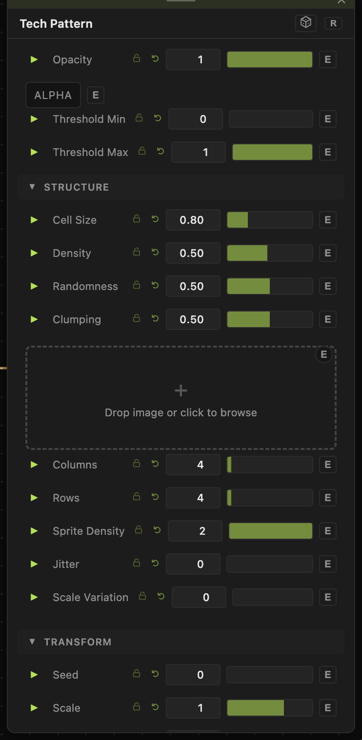
Opacity, Blend Mode, ALPHA, Invert Alpha, Threshold Min / Threshold Max — the standard operator header; see Perlin Noise for details.
Structure
- Cell Size (0.1–3, default 0.8) — the grid cell size; smaller values pack in more glyphs.
- Density (0.05–1, default 0.5) — the fraction of cells that hold a glyph.
- Randomness (0–1, default 0.5) — how much the glyph choice and placement vary per cell.
- Clumping (0–1, default 0.5) — biases the density noise so glyphs gather into clusters rather than spreading evenly.
Sprite Sheet
- Sprite Mode — Default Pattern (built-in glyphs) or Sprite Sheet (frames from an atlas). The sprite controls below only take effect in Sprite Sheet mode.
- Sprite Sheet — the image file to slice into frames (drop an image or click to browse).
- Columns / Rows (1–64) — the atlas grid layout.
- Anim Speed, Random Cycle, Sprite Density, Jitter, Scale Variation, Noise Opacity — control how frames are picked, animated, and placed across the grid.
Transform
- Seed (0–99999) and the shared Scale / Offset / Rotation block.
Dynamics
- Playback is driven by the global animation speed and, in Sprite Sheet mode, Anim Speed.
Every slider has a per-parameter animation bar, so any of these can be animated, audio-driven, or MIDI-mapped — see Parameters and Controls.
Troubleshooting
Sprite sheet shows nothing — set Sprite Mode to Sprite Sheet, then either drop an image into Sprite Sheet or wire a generator into the Sprite Atlas port, and check Columns / Rows match the atlas.
Glyphs spread too evenly — raise Clumping to gather them into clusters, or lower Density.
Grid feels too sparse — lower Cell Size and raise Density.