PCB
Procedural circuit-board generator that scatters components and routes traces between them, with image-driven density and optional animated pulses.
The PCB node generates a procedural circuit board: it scatters components, routes 90°/45° traces between them, and draws pads and glow. It can follow an image wired into its Drive input, and optionally run data pulses along the traces. The layout is static — reseed to change it.
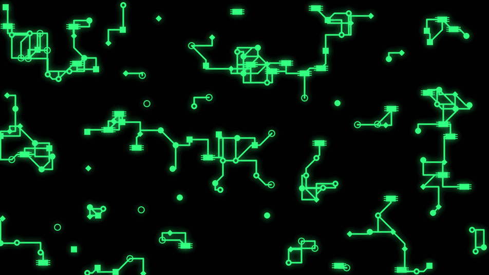
- One texture output; five optional texture inputs (Drive, Mask, Pull, Turbulence, Composite)
- Multiple Route Modes, with component/trace/pad/glow and color controls
- Optional animated data pulses over the static layout
- Found in the node graph under Generators as PCB
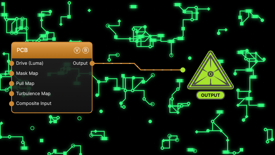
The image on the right is the example patch itself — drag and drop it onto the app (or load it with File → Load) to open the full graph.
Inputs and outputs
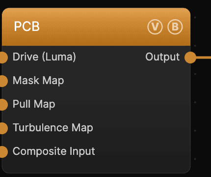
| Port | Type | Purpose |
|---|---|---|
| Drive (Luma) | Texture | Luminance drives where components scatter; in Traces mode, traces follow the shape's outline |
| Mask Map | Texture | Restricts where connections can form |
| Pull Map | Texture | Pulls nodes toward its bright areas |
| Turbulence Map | Texture | Adds local turbulence to routing |
| Composite Input | Texture | Composited over the output using Blend Mode and Opacity |
| Output | Texture | The circuit board |
Parameters
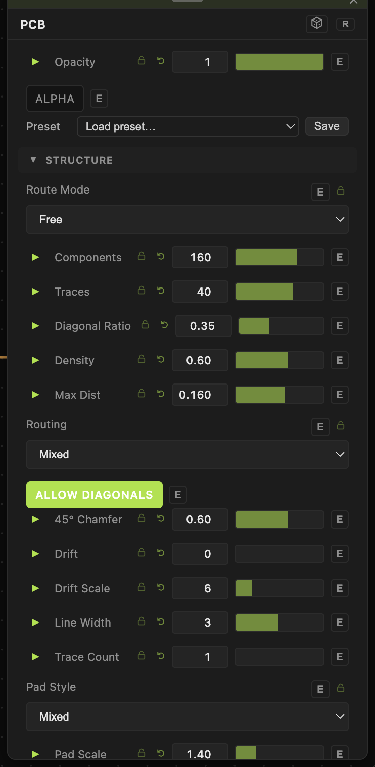
PCB has a large parameter set; the controls shown depend on the selected Route Mode.
Opacity, Blend Mode — the standard operator header; see Perlin Noise.
Structure
- Seed (0–9999, default 1) — reseeds the whole layout.
- Route Mode — Free / Strict (component-and-route board), Dir (directional runs), Flow (flowing spread), or Traces (distance-transform iso-contours of the Drive shape). The controls below change with the mode.
- Components (4–800, default 160) — how many parts are scattered (Free/Strict). Traces (default 40) — how many trace runs. Spacing, Max Dist, Diagonal Ratio — routing geometry.
Style
- Line Width (0.5–20, default 3) — trace thickness. Pad Style (Mixed, Solid, Ring, Via, Chip, Square, Diamond, Cross) and Pad Scale — the junction pads.
- Glow, Glow Strength, Glow Blend — the trace glow.
Color
- Color — Accent (single color), Gradient (two-color), or Sample (from the Drive image). Trace Color (default green) and Background.
Animation
- Animate — turn on data pulses that travel the traces. Flow Speed, Pulse Spacing, and Glow Pulse shape the motion. The board layout itself stays fixed.
Every slider has a per-parameter animation bar, so any of these can be animated, audio-driven, or MIDI-mapped — see Parameters and Controls.
Troubleshooting
Board doesn't move — the layout is static by design; turn on Animate for traveling pulses, and make sure global animation is playing.
Drive image seems ignored — only its luminance matters; raise Drive Amount, and in Traces mode lower Drive Threshold so more of the shape is captured.
Too sparse or too busy — adjust Components / Traces and Density, then reseed.