Circuit Board
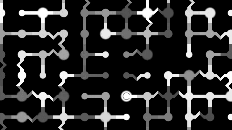
PCB-style trace generator with edge-connected routing, 45-degree dog-leg bends, junction pads, and animated brightness pulses.
The Circuit Board node draws printed-circuit-board traces on a cell grid. Traces connect between neighboring cells, junctions and dead ends get circular pads, and every element pulses in brightness like data flowing through the board.
- One texture output; two optional texture inputs (domain warp and composite)
- Four pattern controls (Cell Size, Line Width, Density, Randomness) plus the standard transform block
- Found in the node graph under Generators in the add-node menu
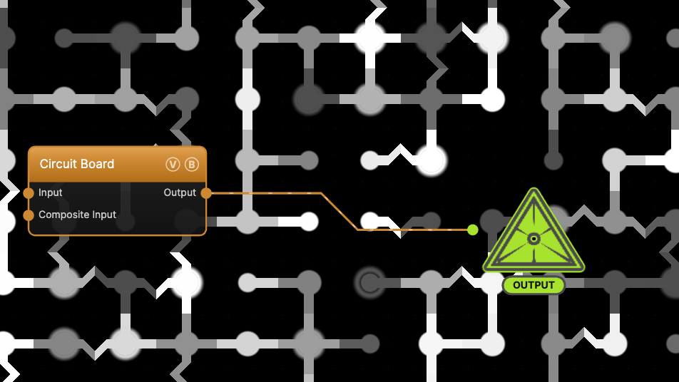
The image on the right is the example patch itself — drag and drop it onto the app (or load it with File → Load) to open the full graph.
Inputs and outputs
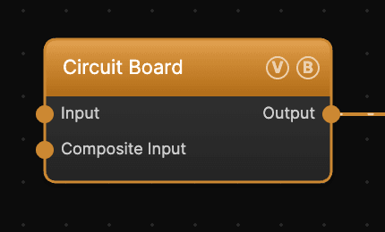
| Port | Type | Purpose |
|---|---|---|
| Displace | Texture | Domain warp: the red and green channels push the sample coordinates by Displace Amount |
| Composite Input | Texture | Composited under the output with Composite Mode and Composite Mix, which appear once the port is wired |
| Output | Texture | The grayscale trace pattern on black |
The warp strength scales with Scale.
Parameters
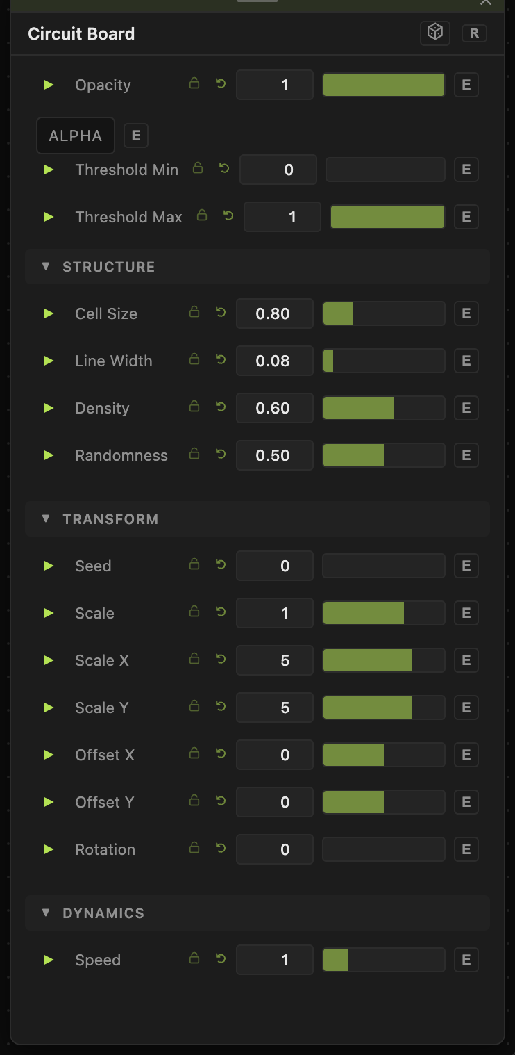
Opacity, Blend Mode, ALPHA, Threshold Min / Threshold Max — the standard operator header; see Perlin Noise for details.
Structure
- Cell Size (0.1–3, default 0.8) — the routing grid pitch. Smaller cells give a denser, finer board.
- Line Width (0–1, default 0.08) — trace thickness relative to the cell. Pad sizes scale with it, so thick lines also mean big pads.
- Density (0.05–1, default 0.6) — the probability that a trace crosses each cell edge. Low values leave isolated fragments; high values wire nearly everything.
- Randomness (0–1, default 0.5) — the probability that a trace ends in a 45° dog-leg bend instead of running straight. 0 gives strictly rectilinear routing.
Transform
- Seed (0–99999), Offset X / Offset Y (−20 to 20), Rotation (0–360) — the shared generator transform block. This generator has no Scale controls; the density comes from its own parameters above.
Dynamics
- Speed (0–5, default 1) — rate of the per-cell brightness pulses. 0 freezes them at their current levels.
Every slider has a per-parameter animation bar, so any of these can be animated, audio-driven, or MIDI-mapped — see Parameters and Controls.
Examples
Dense motherboard — Cell Size 0.3, Line Width 0.06, Density 0.85, Randomness 0.7.
Minimal schematic — Cell Size 1.5, Line Width 0.04, Density 0.35, Randomness 0: sparse, strictly right-angled traces.
Troubleshooting
The board flickers — the brightness pulses are always on at Speed above 0. Set Speed to 0 for a static board.
Traces look disconnected — raise Density; below ~0.3 most cell edges roll no connection and fragments dominate.
For dense multi-component boards with junction dots, see the Trace Network generator; for baked, high-detail circuit art, see the PCB generator.